The Control Stack: From Stick to Prop
Executive Summary
When you move the sticks on your radio, you aren't moving the servos directly. You are feeding a request into the top of a complex "Cascade Controller." The pilot (or autopilot) requests a Position or Angle. The controller converts this into a Rate. The Rate controller converts this into Motor Output.
Theory & Concepts
1. The Hierarchy of Constraints
In robotics, you cannot change position without first changing velocity, and you cannot change velocity without first changing acceleration.
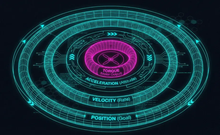
- Mode Layer: Defines the Goal (e.g. "Stay at 10m").
- Position Layer: Defines the Velocity needed to reach the goal.
- Attitude Layer: Defines the Acceleration (Lean Angle) needed to reach the velocity.
- Rate Layer: Defines the Torque needed to reach the angle.
2. Time Constants & Loop Rates
The stack is organized by frequency.
- Outer Loops (Position): Slow and stable. If they run slightly late, the drone drifts a few centimeters.
- Inner Loops (Rate): Fast and critical. If they run late, the drone oscillates or flips.
- Why this matters: This is why ArduPilot prioritizes the Rate Controller as a
FAST_TASKin the scheduler.
The Main Loop (400Hz)
The heartbeat of ArduCopter is the fast_loop.
- Frequency: Typically 400Hz (every 2.5 milliseconds).
- Execution: Every cycle, the scheduler runs the following critical tasks in order:
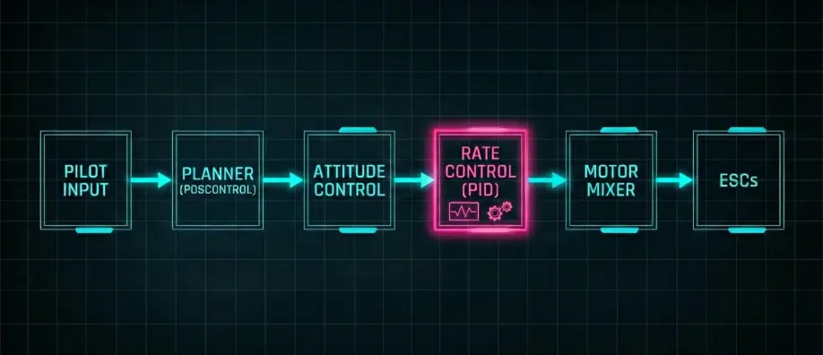
1. The High-Level Planner (update_flight_mode)
- Input: Pilot Sticks, Waypoints, Fence.
- Logic: "Where do I want to be?"
- Output: Target Lean Angles (Roll/Pitch) & Climb Rate.
- Libraries:
AC_WPNav,AC_PosControl.
2. The Attitude Controller (run_rate_controller)
- Input: Target Lean Angles.
- Logic: "How fast do I need to rotate to get to that angle?"
- Output: Target Rotation Rates (Deg/s).
- Libraries:
AC_AttitudeControl.
3. The Rate Controller (Inner Loop)
- Input: Target Rates vs Gyro Rates.
- Logic: "How much power do the motors need to achieve this rotation speed?"
- Output: Normalized Motor Throttle (0.0 to 1.0).
- Technique: PID + FeedForward.
4. The Mixer (motors_output)
- Input: Roll, Pitch, Yaw, Throttle (0-1).
- Logic: "Which motors need to spin to create this torque?"
- Output: PWM / DShot pulses to ESCs.
- Libraries:
AP_Motors.
Data Types
- Position/Velocity:
Vector3f(North, East, Down). - Attitude:
Quaternion(Rotation from Earth to Body frame). - Rates:
Vector3f(Radians/second).
Source Code Reference
- Scheduler Table:
Copter::scheduler_tasks[] - Loop Runner:
AP_Vehicle::loop()