The Output Map: SERVOn_FUNCTION
Executive Summary
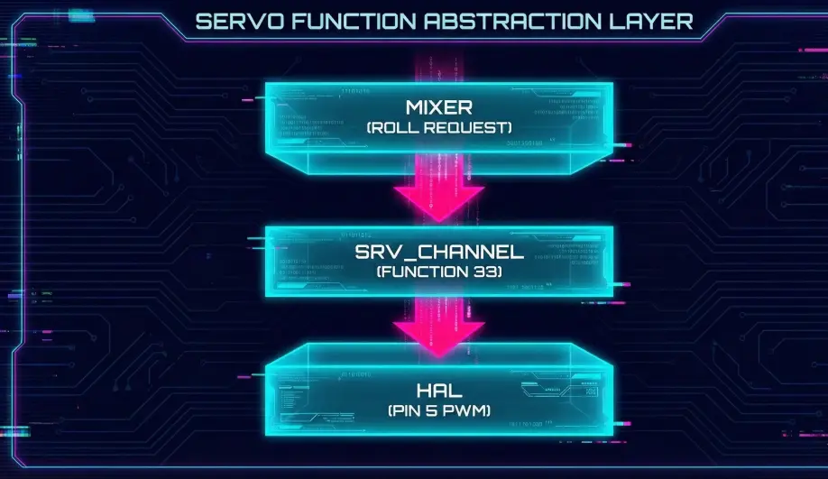
In ArduPilot, "Motor 1" is not physically tied to "Pin 1". Instead, there is a layer of abstraction called SRV_Channels. The Motor Mixer outputs to a logical "Function" (k_motor1), and you map that Function to any physical pin (SERVO5_FUNCTION) using parameters.
Theory & Concepts
1. Hardware Abstraction Layers (HAL)
A Hardware Abstraction Layer is a software bridge between the generic "Autopilot Brain" and the specific "Physical Pins" of a chip.
- The Logic: ArduCopter doesn't know what an STM32 or an H7 chip is. It just knows "Motor 1".
- The Bridge:
SRV_Channelsacts as the dispatcher. This allows the same ArduCopter firmware to run on hundreds of different boards with different pinouts.
2. Functional Mapping vs. Pin Mapping
- Legacy Systems: You had to plug Motor 1 into Pin 1. If Pin 1 broke, the board was useless.
- ArduPilot: Every pin is universal. If Pin 1 is dead, you can move the wire to Pin 8 and set
SERVO8_FUNCTION = 33. The "Brain" never needs to know the hardware changed.
Architecture (The Engineer's View)
1. The Function Enum
ArduPilot defines a list of ~150 possible output functions in Aux_servo_function_t.
- 33: Motor 1
- 34: Motor 2
- 35: Motor 3
- 36: Motor 4
- ...
- 1: Manual (Passthrough)
2. The Conversion Pipeline (calc_pwm)
When the Mixer says "Motor 1 at 50%", here is what happens:
- Normalization: The mixer outputs a float
0.5. - Scaling:
SRV_Channel::calc_pwm()takes this float. - Endpoint Lookup: It looks up the
SERVOx_MINandSERVOx_MAXparameters for the assigned pin. - Math:
PWM = MIN + (Scaled_Value * (MAX - MIN))- Example:
1000 + (0.5 * (2000 - 1000)) = 1500us.
- Example:
- Trim: If the function uses trim (like a servo surface), it centers around
SERVOx_TRIM.
3. Safety Interlocks
The SRV_Channels library also handles the Safety Switch.
- If the Safety Switch is active,
SRV_Channelsforces the output to0(ordisarmed_pwm), regardless of what the Mixer requests.
Debugging Tips
- "My Motor 1 is on Pin 5": This is valid. Set
SERVO5_FUNCTION = 33(Motor 1). - "My Servo moves backwards": Set
SERVOx_REVERSED = 1. This flips the math logic (1.0 input becomes MIN pwm).
Source Code Reference
- Conversion Logic:
SRV_Channel::calc_pwm() - Function List:
SRV_Channel.h
Practical Guide: Configuring a Gripper (Servo)
Let's say you have a 4-motor quadcopter (Channels 1-4) and you plug a Servo Gripper into Pin 5. You want to control it with Channel 9 on your transmitter.
Step 1: Physical Connection
- Plug the Servo Signal wire into Pin 5 (MAIN OUT 5).
- Warning: Most Autopilots do NOT provide 5V power on the servo rail. You must use a separate BEC to power the servo's Red/Black wires.
Step 2: Function Mapping
Tell ArduPilot what Pin 5 is.
- Parameter:
SERVO5_FUNCTION - Value: 59 (
RCIN9). - Meaning: "Whatever PWM value comes in from Radio Channel 9, send it directly to Output Pin 5."
Step 3: Endpoints
Servos burn out if you drive them too far.
- Open the Gripper: Toggle your switch. If it buzzes, reduce
SERVO5_MAX(e.g., from 1900 to 1800). - Close the Gripper: Toggle switch back. If it buzzes, increase
SERVO5_MIN(e.g., from 1100 to 1200).
Step 4: Reversing
If the switch is backwards (Up = Closed, Down = Open):
- Parameter:
SERVO5_REVERSED - Value: 1.