Electronic Speed Controllers (ESCs): The Power Translators
CRITICAL The ESC is the most hardworking computer on your aircraft. It must perform thousands of calculations per second to manage the violent collapse of magnetic fields, all while sitting millimeters away from high-current noise that would blind a lesser device. In the ArduPilot ecosystem, the ESC has evolved from a simple power switch into a sophisticated sensor that dictates the quality of your flight.
1. Commutation Physics: The Invisible Dance
Brushless motors (BLDC) are fundamentally three-phase AC motors powered by a DC battery. The ESC's job is to translate that DC into a rotating magnetic field.
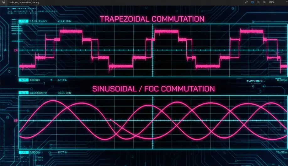
1.1 The Six-Step Dance (Trapezoidal)
Most standard ESCs (BLHeli_S, BLHeli_32) use Trapezoidal Commutation.
- The Method: At any given microsecond, the ESC energizes two of the three motor wires. One is "High" (Positive), one is "Low" (Negative), and the third is "Floating."
- The "Listen" Phase: The ESC uses the floating wire as a sensor. As the permanent magnets on the motor bell sweep past the coils, they induce a tiny voltage in that floating wire (Back-EMF).
- The Trigger: The ESC waits for this voltage to cross zero. This "Zero Crossing" tells the ESC exactly where the rotor is, allowing it to "fire" the next step in the sequence perfectly.
- The Compromise: Because this switching is digital (on/off), the current flow is "choppy." This creates Torque Ripple—microscopic vibrations that you can hear as a "whine" and your gyro can hear as "noise."
1.2 The Silent Path (Sinusoidal / FOC)
Higher-end ESCs (like the APD F-Series or AM32 in Sine mode) use Field Oriented Control (FOC).
- The Method: Instead of on/off switching, the ESC drives all three wires continuously with varying voltages to create a smooth Sine Wave.
- The Benefit: Operation is nearly silent. Torque is consistent throughout the rotation, reducing the vibration floor of the entire airframe. For high-end cinema rigs where every vibration ruins a shot, FOC is mandatory.
2. Protocols: The DShot Revolution
In the early days, we used PWM (Pulse Width Modulation). It was a messy, analog-style system where the length of a pulse determined the speed. If electrical noise "stretched" a pulse, the motor sped up unexpectedly. You had to "calibrate" ESCs to teach them what 0% and 100% looked like.
2.1 The Digital Certainty of DShot
DShot (Digital Shot) changed everything. Instead of pulses, the Flight Controller sends a 16-bit digital packet.
- The Packet:
[11 bits Throttle] [1 bit Telemetry Request] [4 bits Checksum] - Why it wins: Because it is digital, it is immune to noise. The ESC either receives the exact number "1024" (50% throttle) or the checksum fails and it ignores the packet. There is no "drifting" or "guessing." Calibration is dead.
2.2 Bidirectional DShot: The Magic Bullet
This is the single most important feature for an ArduPilot builder.
- The Loop: Immediately after receiving a command, the ESC sends a packet back to the FC on the same wire, reporting the exact RPM of the motor.
- The Result: ArduPilot now knows exactly how fast every motor is spinning 400+ times per second.
- The Harmonic Notch: ArduPilot uses this data to center a digital "Notch Filter" on the motor frequency. If your motor is creating noise at 182Hz, the filter tracks it to 182Hz and deletes it. This allows you to run higher PID gains and get "locked-in" flight without the motors getting hot.
3. Firmware Ecosystem: Choosing Your Brain
Not all ESCs speak the same language. The firmware determines the feature set.
3.1 BLHeli_S (8-bit)
- Hardware: Older BB21 or BB51 chips. Found on budget AIO boards and "Whoop" ESCs.
- The Limitation: The stock firmware is outdated and cannot handle Bidirectional DShot efficiently.
- The Fix: You MUST flash Bluejay Firmware. This is an open-source project that "unlocks" these 8-bit chips, enabling Bi-DShot and variable PWM frequencies (48kHz/96kHz) for smoother flight and longer battery life.
3.2 BLHeli_32 (32-bit)
- Hardware: STM32L4 or F0 chips. The standard for high-performance builds from 2017-2024.
- Status: Closed Source & Dead. The developer ceased operations in 2024 due to geopolitical sanctions.
- Legacy: Existing ESCs work fine, but there will be no future updates or bug fixes.
3.3 AM32 (The Future)
- Status: Open Source.
- Platform: Runs on generic 32-bit MCUs (STM32, AT32).
- Features: It is the spiritual successor to BLHeli_32, offering advanced features like Sine Startup, Variable PWM, and S-Port telemetry. New hardware is increasingly shipping with AM32 pre-installed.
4. Practical Build Strategy: Stacks vs. Individuals
4.1 The 4-in-1 ESC (The "Stack")
- Pros: Clean wiring, compact, lighter.
- Cons: The Chain Reaction. If you blow one MOSFET on motor #3, you have to throw away the entire $80 board.
- Thermal Trap: All four ESCs are on one PCB. In a heavy-lift hover, they heat each other up.
4.2 Individual ESCs (On the Arms)
- Pros: Thermal isolation (they are cooled by the prop wash). Repairability (replace one at a time).
- Cons: Messy wiring. Requires a Power Distribution Board (PDB).
- Verdict: Use Stacks for 5" freestyle and racing. Use Individual ESCs for 7"+ long-range or professional heavy-lift rigs.
5. The Capacitor: The Inductive Spike
CRITICAL: Every time the ESC switches off a phase, the magnetic field in the motor collapses. This generates a high-voltage spike (Inductive Kickback).
- Active Braking: When you lower the throttle, the ESC actively brakes the motor (Damped Light). This turns the motor into a generator, dumping massive energy back into the power wires.
- The Danger: This "Ripple Voltage" can spike to 35V on a 4S system or 50V+ on a 6S system.
- Result: It blows the 5V regulator on your Flight Controller, or burns out the Video Transmitter.
- The Fix: You MUST solder a Low-ESR Electrolytic Capacitor (e.g., 1000uF 50V) directly to the ESC battery pads.
- The Trap: Do not solder it to the XT60 pigtail. The wire length adds inductance that prevents the capacitor from "catching" the spikes. It must be at the source of the noise: the ESC pads.
6. ArduPilot Integration: Key Parameters
MOT_PWM_TYPE
- Selection: Set to 6 (DShot600).
- DShot300 vs DShot600: DShot600 is faster, but if you have long signal wires or a noisy build, DShot300 is more robust against packet loss.
SERVO_BLH_AUTO
- Passthrough: Set to 1 (Enabled).
- The Function: This allows you to connect your Flight Controller to your PC via USB, and then use the BLHeli Configurator or ESC-Configurator (web) to flash your ESCs. The FC acts as a bridge. You do not need a separate programmer.
SERVO_DSHOT_ESC (Pole Count)
- The Math: The ESC reports Electrical RPM (eRPM). ArduPilot needs Mechanical RPM.
- Formula:
Mechanical_RPM = eRPM / (Pole_Count / 2) - Configuration: You must set the number of magnetic poles (count the magnets on the bell). Typically 14 for 5" motors. If this is wrong, your Harmonic Notch Filter will target the wrong frequency, and your drone may vibrate or fly away.