Power Systems Engineering: The Foundation of Flight
CRITICAL The power system is the most dangerous component of your aircraft. A failure here is rarely a "glitch"—it is usually a fire or a "dead stick" crash from 400 feet. In autonomous flight, where the computer (FC) depends on a stable voltage rail to think, the power system is the literal foundation of the mission.
1. Battery Chemistry: Energy vs. Power
Not all Lithium is created equal. The choice between LiPo and Li-Ion is a trade-off between Burst Power and Total Endurance.
1.1 Lithium Polymer (LiPo)
The standard for performance flight.
- The Structure: Soft foil pouches stacked together. This maximizes surface area, allowing for extremely high discharge rates.
- The IR (Internal Resistance): Very low (< 3 milli-Ohms per cell).
- The Personality: LiPos can dump their entire energy payload in under 2 minutes. They provide the "punch" needed for aggressive maneuvers or heavy lifting.
- The Danger: If punctured or overcharged, the foil pouches can "vent with flame" (thermal runaway). Always store and charge in a fireproof container.
1.2 Lithium Ion (Li-Ion)
The standard for long-range cruising.
- The Structure: Cylindrical metal cans (18650 or 21700).
- The Superpower: Massive energy density. A 21700 pack can hold 2x the energy of a LiPo of the same weight.
- The Limitation: High Internal Resistance (> 15 milli-Ohms). If you try to pull 100 Amps from a Li-Ion pack, the voltage will "sag" so low that the Flight Controller will reboot, and the internal heat will likely damage the cells.
- Use Case: Missions requiring 30+ minutes of flight at steady, low throttle.
2. The C-Rating Lie: How to Protect Your Wallet
Most battery labels are pure marketing. A "150C" label is physically impossible; the 12AWG wires on the battery would melt into slag at that current.
2.1 The Physics of Internal Resistance (IR)
The true health of a battery is measured in milli-Ohms (mΩ), not "C-Rating."
- New Battery: 1-3 mΩ per cell.
- Dying Battery: 10+ mΩ per cell.
- The Diagnostic: Most modern chargers (like ISDT or SkyRC) can measure IR during charging. If one cell has a significantly higher IR than the others, that battery is a "fire in waiting." Retire it.
2.2 Calculating Real-World Limits
The true limit is determined by the Internal Resistance (IR) and the thermal mass.
- Formula:
Max Amps = sqrt(Watts_dissipated / IR) - Rule of Thumb:
- "100C" label ≈ 35-40C Real World.
- "50C" label ≈ 20-25C Real World.
- Plan your build assuming 30C max continuous draw.
3. Impedance Matching: Connectors & The "Spark"
The connector is the smallest part of your drone, but it carries the most load. It is a resistor. If it gets hot after a flight, it is too small.
3.1 Connector Hierarchy
- XT30: Rated for 30A. Use on 2-3" micro drones.
- XT60: Rated for 60A. The global standard for 5" drones.
- XT90: Rated for 90A. Mandatory for 7" and X-Class builds.
- AS150: 7mm Anti-Spark bullets. Mandatory for 12S (50V) industrial rigs.
3.2 The Anti-Spark Solution
When you plug in a 6S (25V) battery, the capacitors on the ESCs charge instantly, creating a plasma arc (the "pop"). This arc erodes the gold plating on your connectors, increasing resistance.
- The Fix: Use XT90-S or AS150 connectors. They have a built-in resistor that pre-charges the system before the final metal-to-metal contact is made. This preserves your connectors and your electronics.
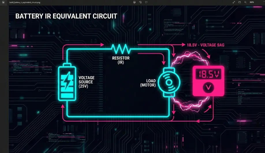
4. Voltage Sag Physics
Voltage Sag is the difference between your battery's resting voltage and the voltage the FC sees under load.
Formula: V_drop = Current * Resistance
The Scenario
- Battery: 6S LiPo (25.2V).
- IR: 0.02 Ohms (20mΩ).
- Connector/Wire Resistance: 0.003 Ohms.
- Throttle Punch: 100 Amps.
The Calculation
V_drop = 100 * (0.02 + 0.003) = 2.3 Volts
- Result: The instant you hit full throttle, your voltage drops to 22.9V.
- Implication: Your motors lose RPM (since RPM = Kv * Volts). The drone feels "soft."
- Mitigation:
- Keep Warm: IR increases dramatically when cold. Pre-heat packs in winter.
- Parallel Packs: Running two packs in parallel halves the total IR (
1/Rt = 1/R1 + 1/R2), reducing sag by 50%.
5. ArduPilot Integration: Power Monitoring
The Flight Controller needs to know the voltage and current to calculate remaining flight time and failsafe conditions.
5.1 BATT_MONITOR
- Setting: Usually set to 4 (Analog Voltage and Current).
- Calibration: Do not trust the factory numbers. Measure your battery with a multimeter, then adjust
BATT_VOLT_MULTin ArduPilot until the Mission Planner HUD matches your multimeter exactly.
5.2 BATT_FS_LOW_VOLT (The Lifeboat)
- Function: This triggers a Return-to-Launch (RTL) or Land when the battery is low.
- Rule: Set this to 3.5V per cell (21.0V for 6S).
- Why? If you set it lower, you might not have enough "reserve energy" to fight a headwind on the way home. It is better to land early than to drop from the sky.
5.3 BATT_AMP_PERVLT
- Function: Calibrates the current sensor.
- Method: Fly a battery, note how many mAh ArduPilot thinks it used, then look at how many mAh your charger puts back in. If the charger says 1000mAh and ArduPilot says 800mAh, you need to adjust this multiplier to ensure your "Fuel Gauge" is accurate.