DroneCAN: The Modern Bus
Executive Summary
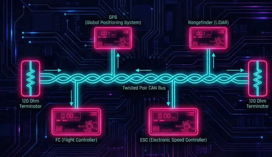
I2C and UART are legacy protocols. They are point-to-point, prone to noise, and have no standard configuration interface. DroneCAN (formerly UAVCAN v0) is a robust, differential-signaling bus. It allows you to daisy-chain GPS, Compass, ESCs, and Rangefinders on a single twisted pair of wires. It features "Plug and Play" node allocation and centralized configuration.
Theory & Concepts
1. Publish / Subscribe Architecture
MAVLink is often Request/Response. DroneCAN is Pub/Sub.
- Publisher: A GPS node broadcasts
uavcan.equipment.[gnss](/field-manual/sensor-architecture/gps-integration.html).Fixmessages on the bus. It doesn't know or care who is listening. - Subscriber: The Flight Controller subscribes to
uavcan.equipment.gnss.Fix. - Benefit: Multiple devices can listen to the same sensor (e.g., a Companion Computer and the Autopilot) without fighting for the serial port.
2. Dynamic Node Allocation (DNA)
On a CAN bus, every device needs a unique 7-bit Address (Node ID).
- The Problem: In manual systems (CANopen), you have to set DIP switches on every device to avoid conflicts.
- The DNA Solution:
- A new device boots up with Node ID 0 (Anonymous).
- It broadcasts a "Hello" message with a 16-byte Unique ID (UUID).
- ArduPilot (The DNA Server) hears this. It looks up the UUID in its database.
- ArduPilot assigns a permanent Node ID (e.g., 55) to that UUID.
- The device saves "55" to flash and uses it forever.
3. SLCAN (Tunneling)
How do you configure a CAN GPS if it doesn't have a USB port?
- The Tunnel: ArduPilot acts as a bridge. It wraps raw CAN frames inside MAVLink packets (
CAN_FRAME). - The Tool: The "DroneCAN GUI Tool" on your PC sends these MAVLink packets. ArduPilot unwraps them and puts them on the CAN bus. The response follows the reverse path.
- Result: You can update firmware and change settings on a GPS module while it is installed in the drone.
Key Parameters
| Parameter | Default | Description |
|---|---|---|
CAN_P1_DRIVER |
0 | 1=First Driver. Enables the CAN interface. |
CAN_D1_PROTOCOL |
1 | 1=DroneCAN. |
GPS_TYPE |
9 | 9=UAVCAN. Tells ArduPilot to look for GPS on the CAN bus. |
Source Code Reference
- DNA Server:
AP_DroneCAN_DNA_Server::handle_allocation()
Practical Guide: Configuring CAN Nodes (SLCAN)
You bought a Here3 GPS. How do you change its LED color? You can't plug it into USB. You must tunnel through the Autopilot.
Step 1: Enable the Driver
- Set
CAN_P1_DRIVER = 1. - Set
CAN_D1_PROTOCOL = 1(DroneCAN). - Reboot.
Step 2: Establish the Tunnel
- Connect Mission Planner via USB.
- Press Ctrl+U (UAVCAN Screen).
- Click "SLCan Mode CAN1".
- What happens: Mission Planner sends a command to ArduPilot to stop acting like a Flight Controller and start acting like a CAN Adapter. The MAVLink stream will die. This is normal.
- You should see a list of nodes appear (e.g., "Here3 GPS", "ZTW ESC").
Step 3: Configure the Node
- Click the "Parameters" button next to the GPS node.
- A new window appears showing the GPS's internal parameters.
- Change
LED_COLORor whatever you need. - Write Params.
- Critical: Reboot the flight controller to exit SLCAN mode and return to normal flight.